Building a Game Boy Link Cable Breakout Board
Right when I started work on Lanette's time capsule, there was one thing I thought might be impossible. There were a lot of things I thought were (and still think are) going to be incredibly hard, but all still possible. The one thing that stuck out and made me think that maybe the Lanette capsule was just a pipe dream was... building a connector.
Of course, for Lanette's time capsule, a connector is needed. There has to be something to plug your link cables into so the cable can be read from and written to. And these aren't off-the-shelf parts we're talking here.
Imagine. You have a cable. A cable which looks a little something like this.
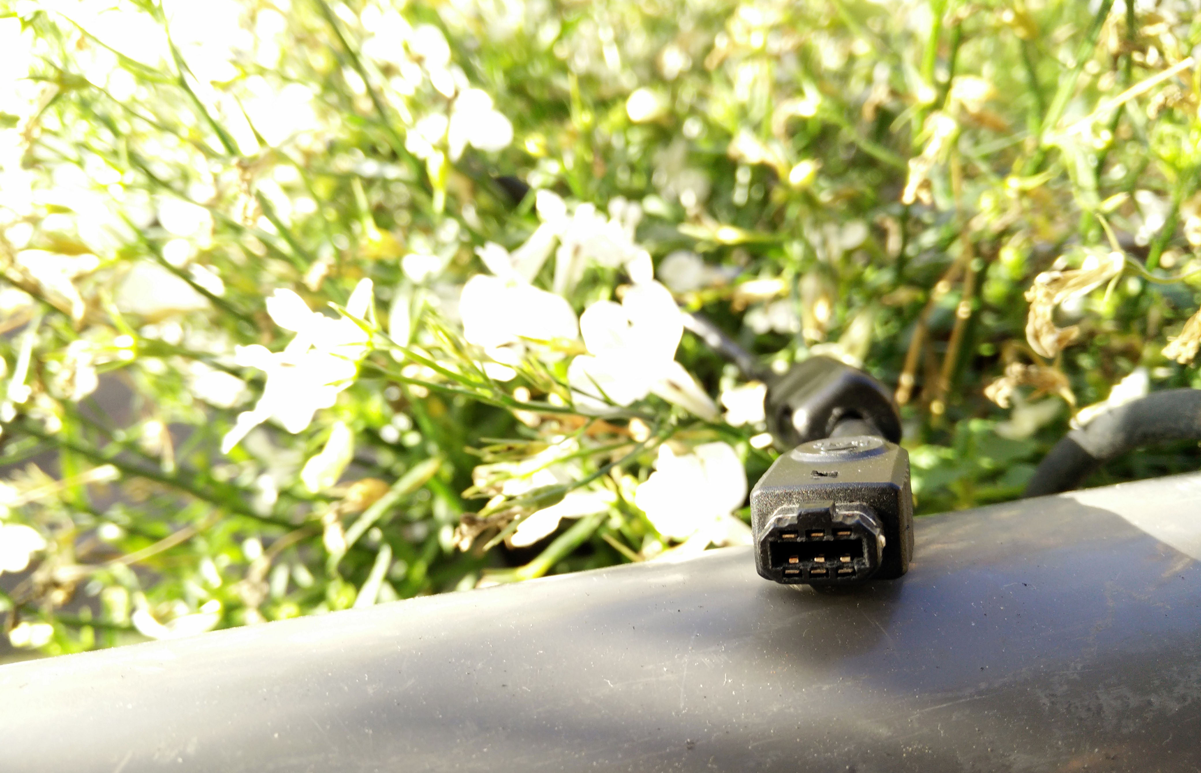
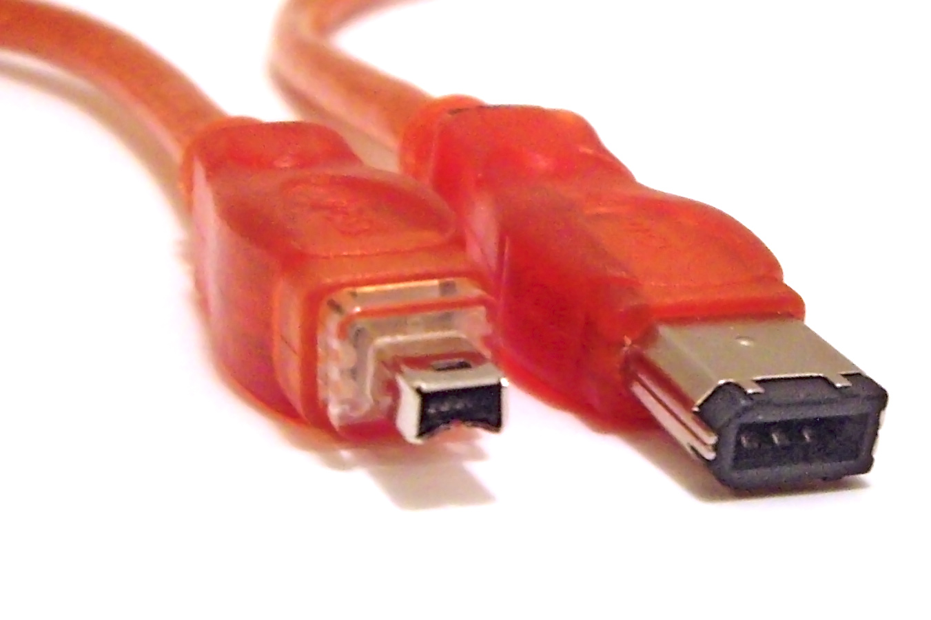
It's... not a standard cable. This is immediately apparent. It looks a bit like a 6-pin FireWire connector (Did you know? FireWire's connector design is actually based on the Game Boy's!), but it's not quite, so FireWire parts won't do the trick. What do you even do? You've got an obscure, proprietary cable, and you most definitely don't have the industrial money or contacts available to make any sort of mold - and you need to build a connector. Just saying the words "build a connector" sounds ridiculous to me. I had no idea where to even start, which made this the part that worried me the most. One of the few steps I manage to take in this phase is looking up the pins - how many there really are, their different configurations on different cables, etc. I find out some wonderful people have already documented all this (rudimentarily, at least), which helps a lot. The exact page linked to here will come into play more later, when we're going to be working with the actual signals. A bit after this I realize I know a semi-professional electronics enthusiast - so I take the fight to him.
I show up at his office, link cable in hand, dried tear tracks of futility running down my cheeks, and I pose him the exact question I myself am trying to figure out. "Hey, David! How the heck do I go about building a connector for this thing?" He looks at it in silence for ten seconds or so, and then makes an unintelligible series of noises along the lines of "wait but uh hmmmm". He produces his trusty calipers (which he has a dedicated case for - that's how you know he's an engineer) and measures the inside of the connector. He then utters the words which transform my legs from a bad kind of jelly to a good kind of jelly.
"Oh! This is easy!"
What he had figured out is that the connector's inner thickness is exactly 1.6mm - which just so happens to be the standard thickness for circuit boards. The result of this is that you can build a connector by simply producing a circuit board with six pads where the pins on the male connector are, and then connect them to anything you want from there. The first thing to do is of course to make a breakout board.
A breakout board, for the uninitiated, is a type of circuit board that connects pins that are hard to access to other pins that are more easily used. The pins on breakout boards are often also helpfully labeled, although that's optional. A breakout board is needed is in order to connect the cable to, say, a breadboard, or directly into a development board (but more on that later, when we get to that part).
So we sit down together, me and David, and design a prototype breakout board in Eagle (Eagle isn't a very good piece of software, but it's free and in a very specialized field, so there ain't much to choose from). Well, he does most of the work as I don't know the first thing about designing circuit boards, but I do learn a lot. Enough to later re-make the design myself, and add a few bells and whistles and improve upon it.
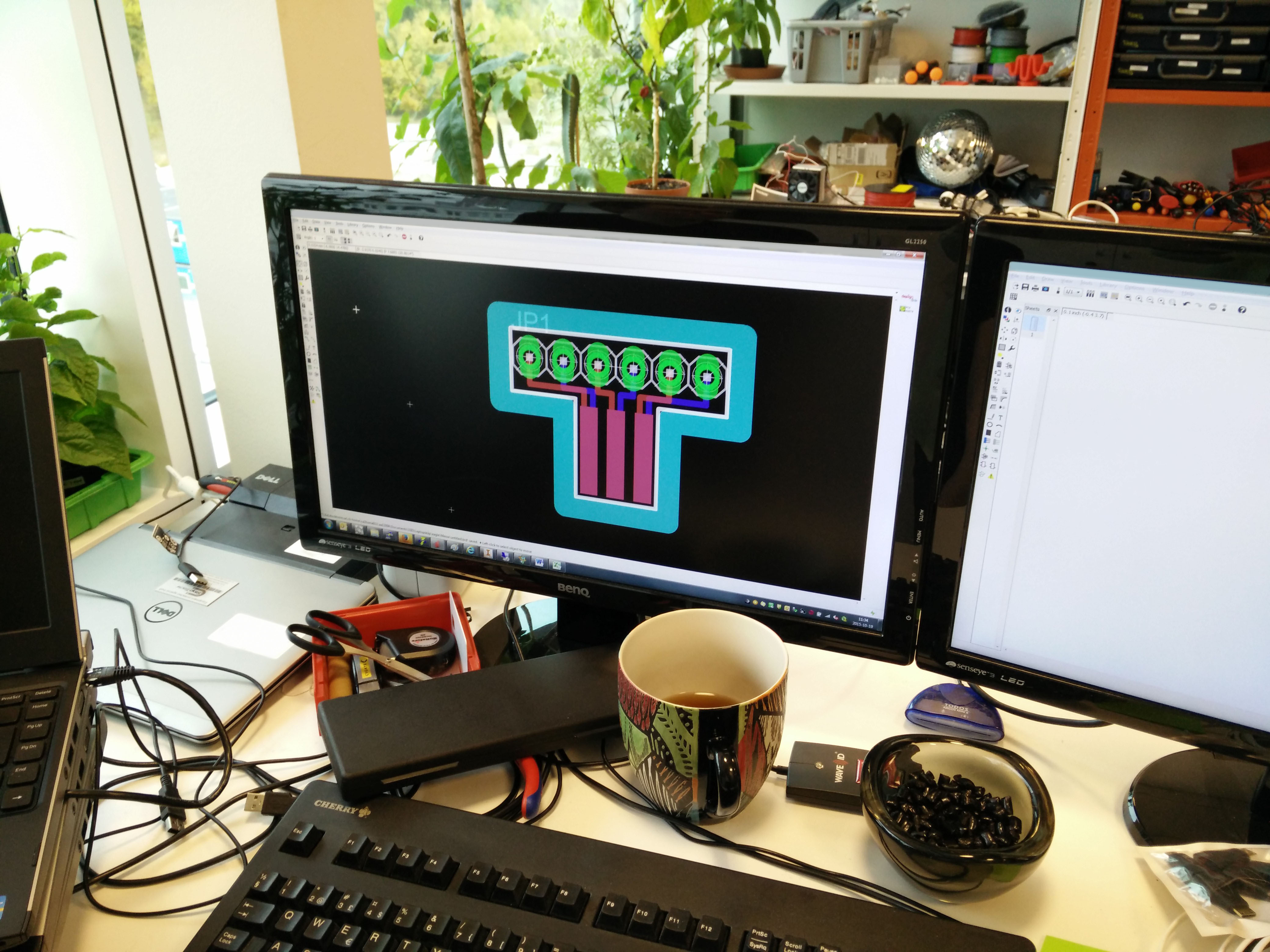 The initial design shown here isn't the exact version I ended up going with, but it's mostly identical.
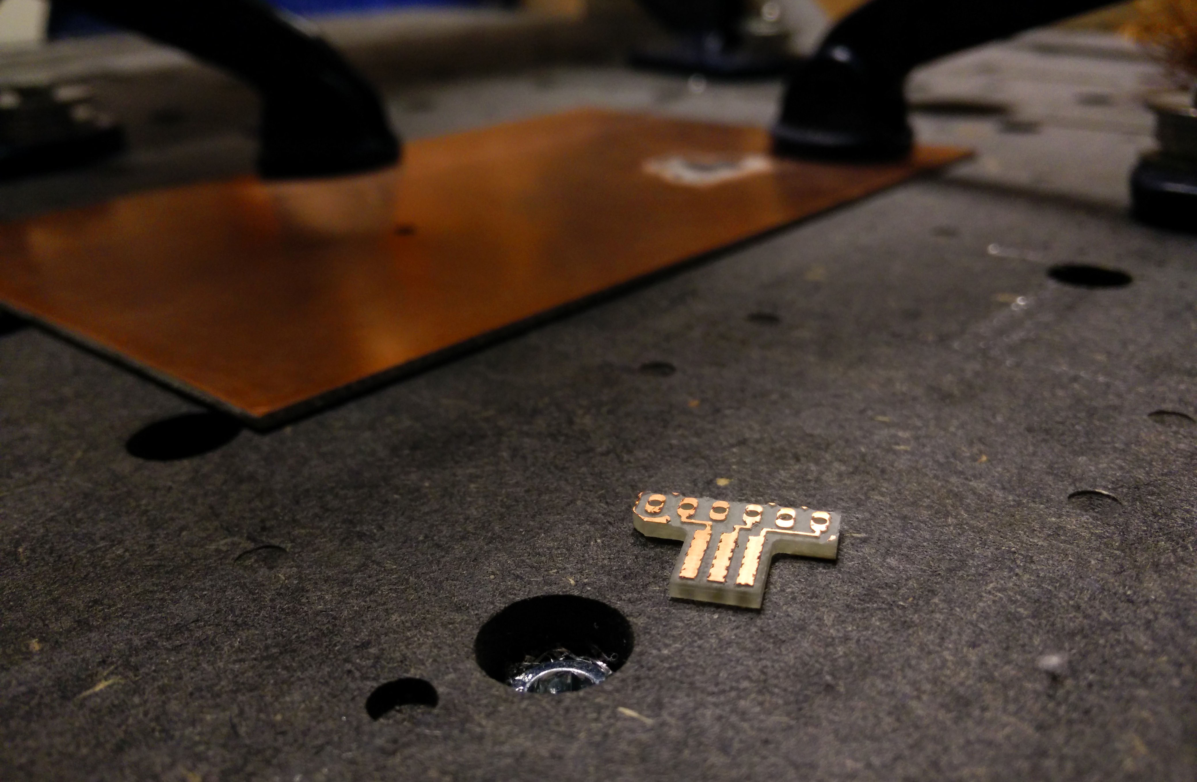
My luck doesn't end here, either. How does a private person make a circuit board? As it turns out, David owns a CNC machine (a computer-controlled mill cutter) for circuit boards, which he is willing to let me use. The next day, I go to cut the boards out. I came home late, but man was it ever worth it. I got a little clip of the CNC in action - distilled those three hours down to a few seconds for you.
Once that is done, I have four almost-finished breakout boards.
As you can probably see, though, one important part is missing: the pins. Without pins, it's awfully hard to actually connect the board to anything. A couple of days after cutting them out, I solder on some pin headers to fix this problem. Since the boards are CNC'd, and the through-holes therefore aren't copper-coated, they need to be soldered on both sides to make a proper connection, which is harder than what would normally have to be done. I haven't soldered a lot until now, so it takes a good while and looks almost entirely terrible, but it works. No harm, no foul.
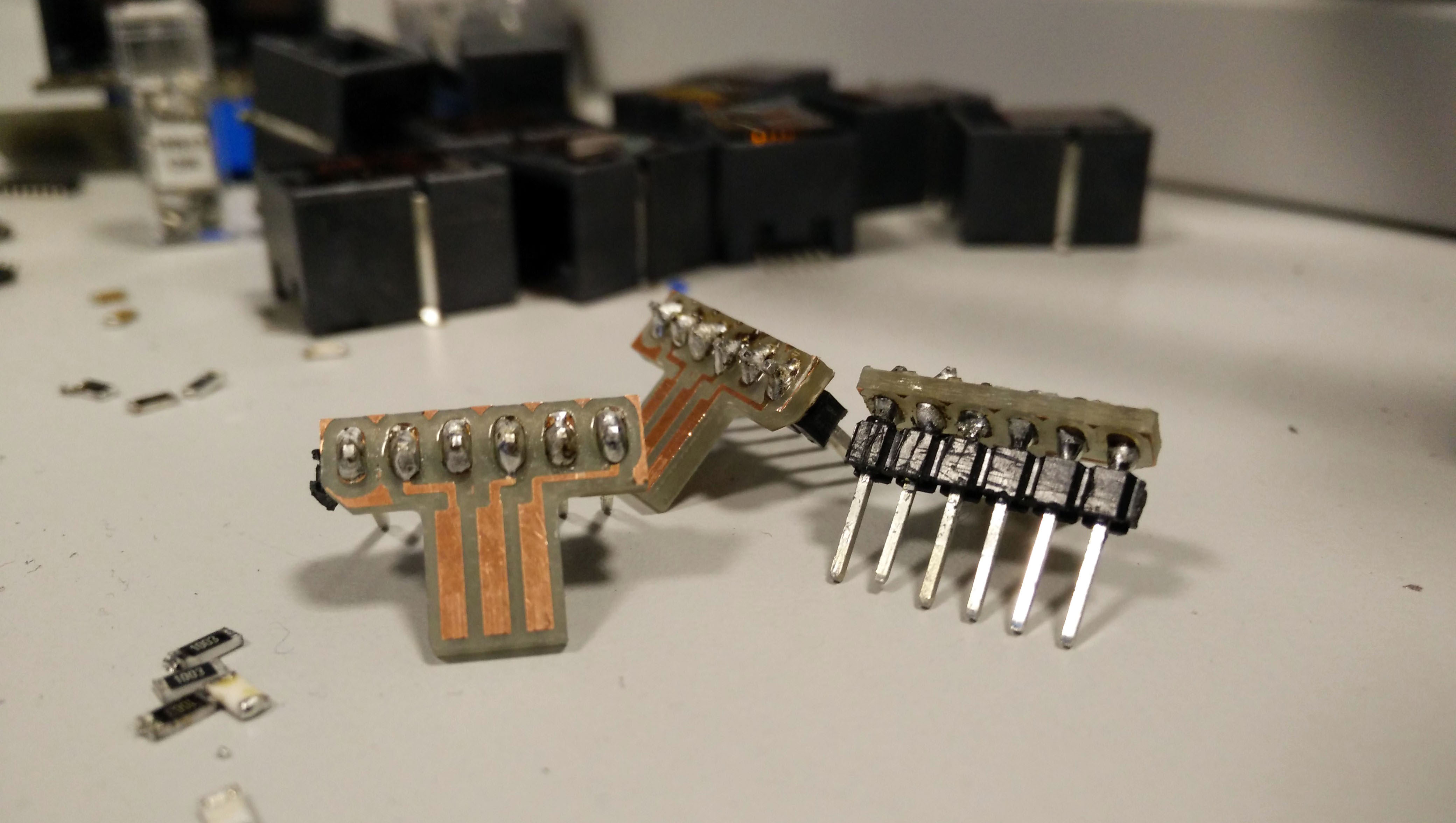 The finished breakout boards.
They all fit perfectly into the link cable, and are ready to be connected to.
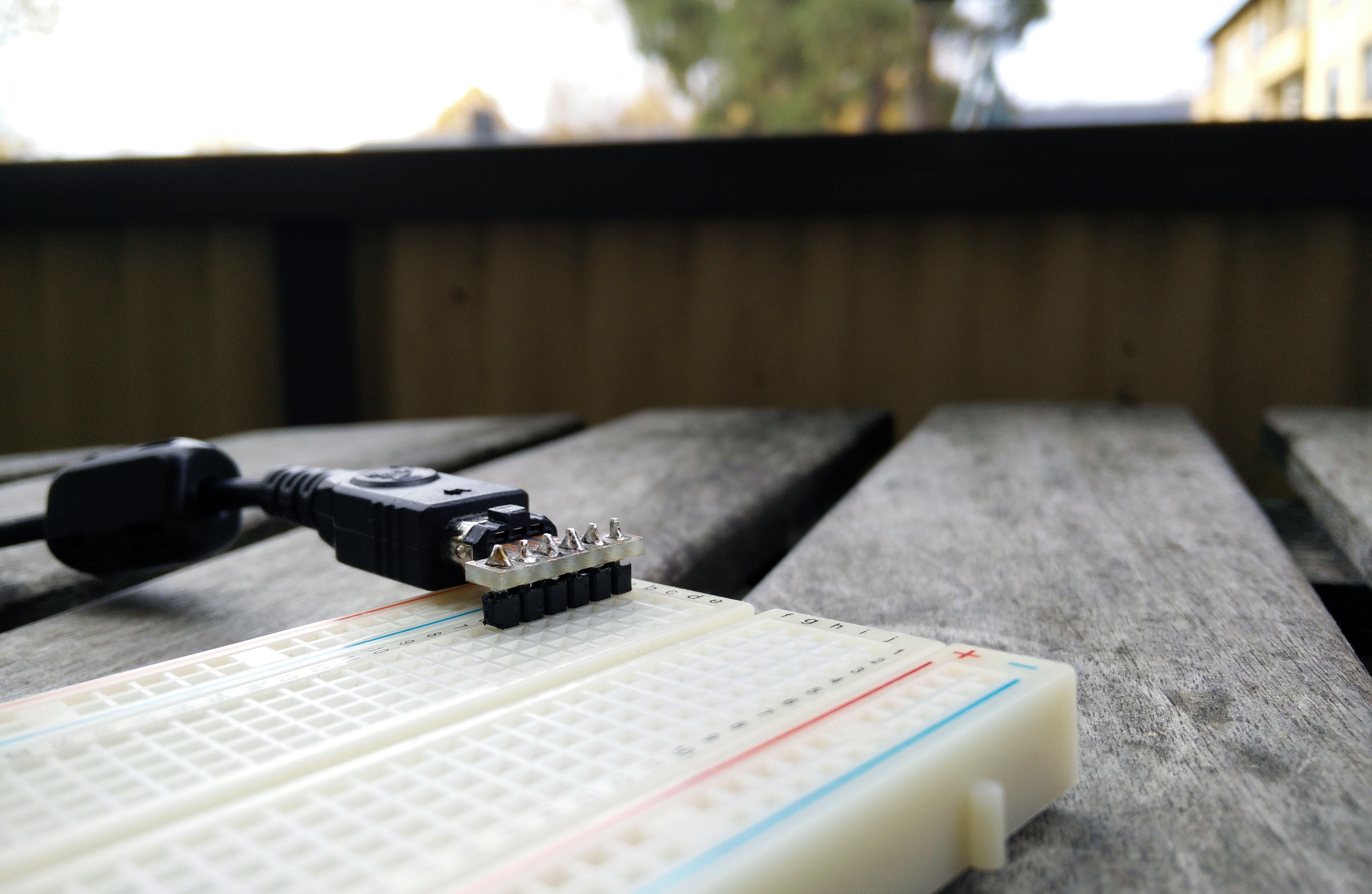 Connection made.
Now that the breakout boards are finished, the link cables are ready to be connected directly to a microcontroller. I'm going to be using a Teensy for the Lanette capsule prototype - more on that at a later date. The Teensy is in the mail on the way here, so sit tight until then!
If you'd like to talk to me, you can do so @obskyr on Twitter, or you can e-mail me - or just comment on this here devlog entry. See you in the next one!